

مراجعة شاملة لتطبيقات وتطورات المكثفات الفائقة
.png)


خلاصة
1. Introduction
2. أساسيات المكثفات الفائقة
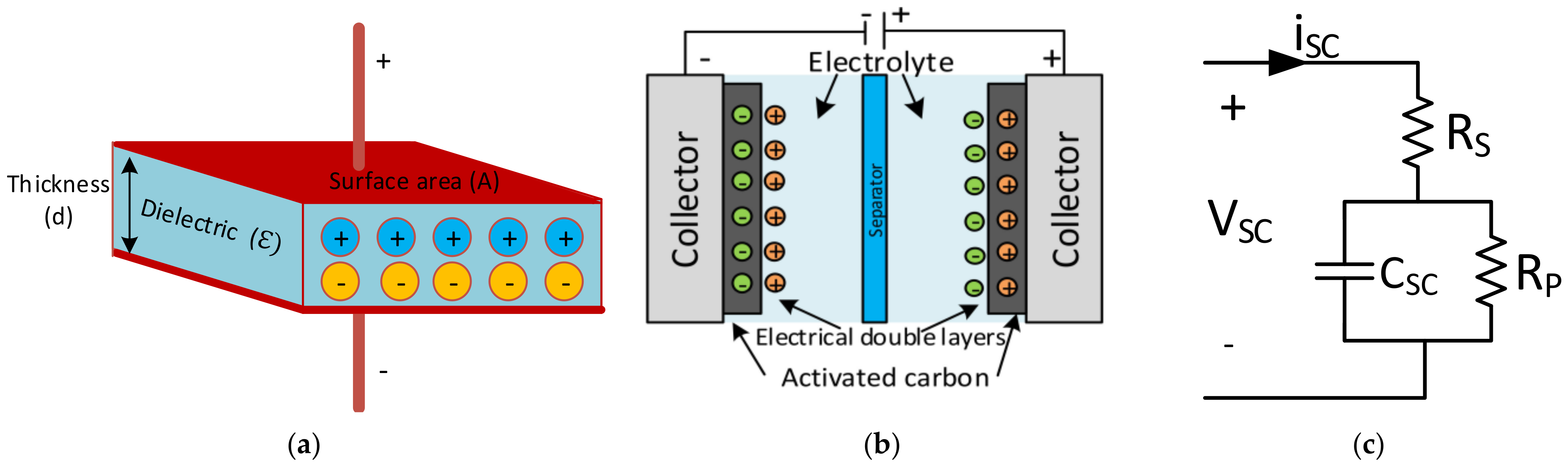
2.1. الهيكل والمواصفات


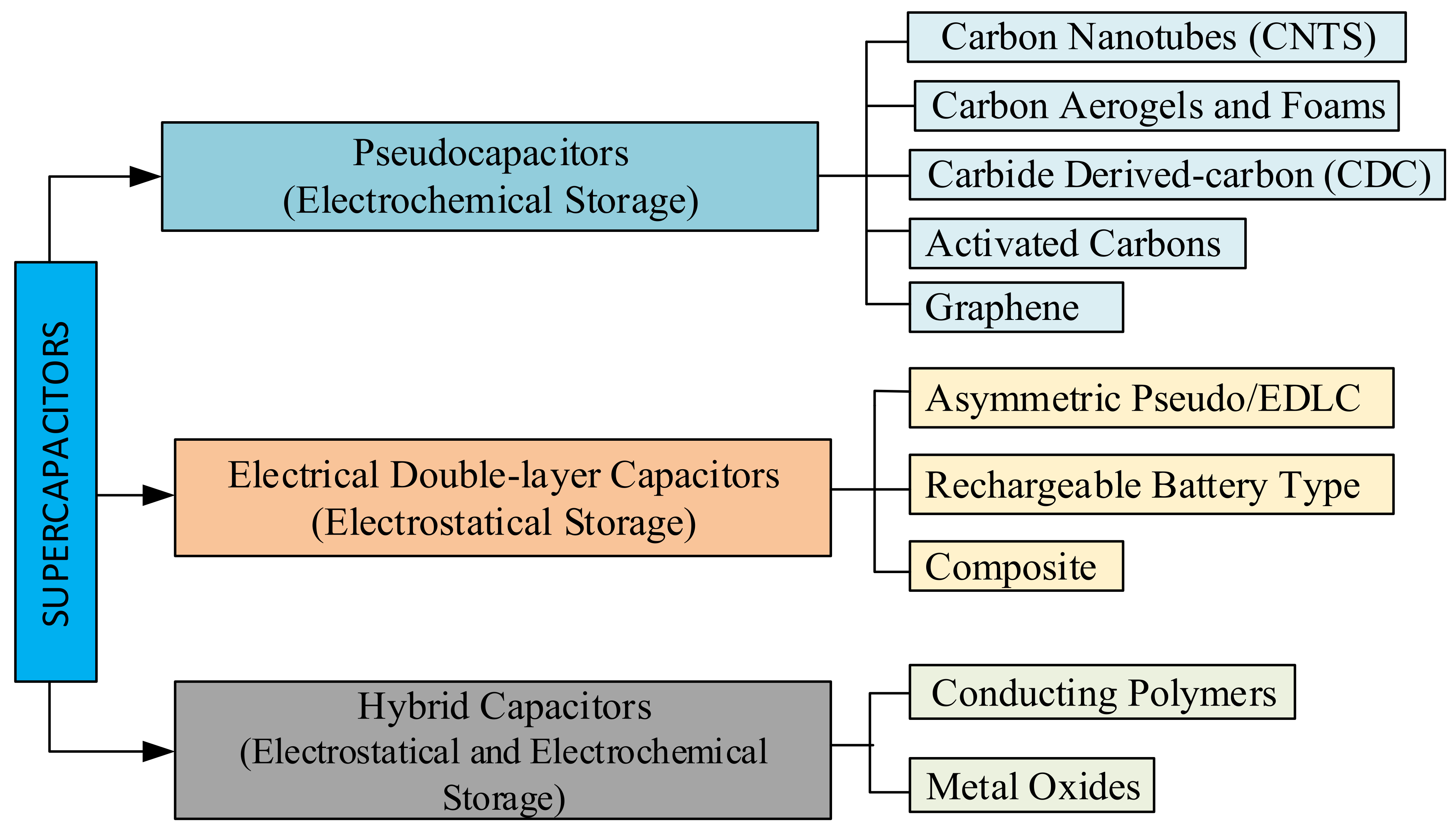
2.2. التصنيفات


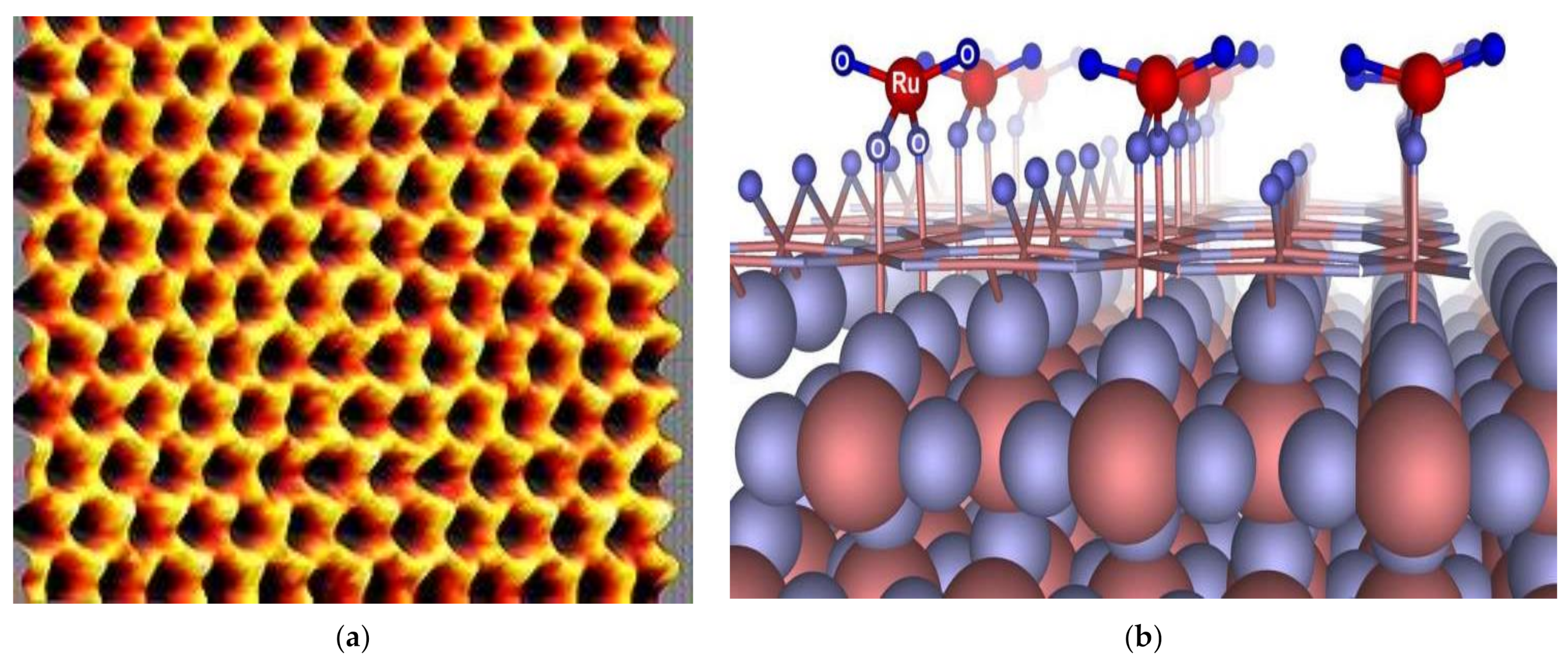
2.3. المواد

3. Techno-Economic Analyses of Supercapacitors


4. Applications of SC


5. Modelling and Performance Tests for SCs


6. Summary of the Literature

7. Conclusions
Author Contributions
Funding
Institutional Review Board Statement
Informed Consent Statement
Acknowledgments
Conflicts of Interest
References
- Novas, N.; Alcayde, A.; Robalo, I.; Manzano-Agugliaro, F.; Montoya, F.G. Energies and Its Worldwide Research. Energies 2020, 13, 6700. [Google Scholar] [CrossRef]
- Smith, S.C.; Sen, P.K.; Kroposki, B. Advancement of energy storage devices and applications in electrical power systems. In Proceedings of the 2008 IEEE Power and Energy Society General Meeting-Conversion and Delivery of Electrical Energy in the 21st Century, Pittsburgh, PA, USA, 20–24 July 2008; pp. 1–8. [Google Scholar]
- Şahin, M.E.; Blaabjerg, F. A hybrid PV battery/supercapacitor system and a basic active power control proposal in MATLAB/Simulink. Electronics 2020, 9, 129. [Google Scholar] [CrossRef] [Green Version]
- Sun, C.; Negro, E.; Vezzù, K.; Pagot, G.; Cavinato, G.; Nale, A.; Bang, Y.H.; Di Noto, V. Hybrid inorganic-organic proton-conducting membranes based on SPEEK doped with WO3 nanoparticles for application in vanadium redox flow batteries. Electrochim. Acta 2019, 309, 311–325. [Google Scholar] [CrossRef]
- Yüksek, Ö.; Anılan, T.; Saka, F. Problems and possible solutions to environmental impacts of small hydropower plants in Turkey. Turk. J. Electromech. Energy 2020, 5, 37–47. [Google Scholar]
- Şahin, M.E. A photovoltaic powered electrolysis converter system with maximum power point tracking control. Int. J. Hydrog. Energy 2020, 45, 9293–9304. [Google Scholar] [CrossRef]
- Zhong, Y.; Xia, X.; Mai, W.; Tu, J.; Fan, H.J. Integration of energy harvesting and electrochemical storage devices. Adv. Mater. Technol. 2017, 2, 1700182. [Google Scholar] [CrossRef]
- Zhang, H.; Sun, C. Cost-effective iron-based aqueous redox flow batteries for large-scale energy storage application: A review. J. Power Sources 2021, 493, 229445. [Google Scholar] [CrossRef]
- Şahin, M.E.; Blaabjerg, F.; Sangwongwanich, A. A review on supercapacitor materials and developments. Turk. J. Mater. 2020, 5, 10–24. [Google Scholar]
- Liu, S.; Wei, L.; Wang, H. Review on the reliability of supercapacitors in energy storage applications. Appl. Energy 2020, 278, 115436. [Google Scholar] [CrossRef]
- Omar, N.; Daowd, M.; Bossche, P.V.D.; Hegazy, O.; Smekens, J.; Coosemans, T.; Mierlo, J.V. Rechargeable energy storage systems for plug-in hybrid electric vehicles—Assessment of electrical characteristics. Energies 2012, 5, 2952–2988. [Google Scholar] [CrossRef] [Green Version]
- Jing, W.; Lai, C.H.; Wong, W.S.H.; Wong, M.L.D. Battery-supercapacitor hybrid energy storage system in stand-alone DC microgrids: A review. IET Renew. Power Gener. 2017, 11, 461–469. [Google Scholar] [CrossRef]
- Sharma, P.; Kumar, V. Current technology of supercapacitors: A review. J. Electron. Mater. 2020, 49, 3520–3532. [Google Scholar] [CrossRef]
- Glavin, M.E.; Hurley, W.G. Optimisations of a photovoltaic battery ultracapacitor hybrid energy storage system. Sol. Energy 2012, 86, 3009–3020. [Google Scholar] [CrossRef]
- Lindenmaier, J.; Stiegler, M.; Kabza, H. Charge/Discharge Load Reduction of Lead Acid Batteries in Micro-Hybrid Vehicles Using Ultra-Capacitor Assistance. In Proceedings of the 24th World Battery, Hybrid and Fuel Cell Electric Vehicle Symposium, Stavanger, Norway, 13–16 May 2009. [Google Scholar]
- Chen, H.; Cong, T.N.; Yang, W.; Tan, W.; Li, Y.; Ding, Y. Progress in Electrical Energy Storage System: A Critical Review. J. Prog. Nat. Sci. 2009, 9, 291–312. [Google Scholar] [CrossRef]
- Omar, N.; Verbrugge, B.; Van den Bossche, P.; Van Mierlo, J. Power and life enhancement of battery-electrical double layer capacitor for hybrid electric and charge-depleting plug-in vehicle applications. J. Electrochim. Acta 2010, 55, 7524–7531. [Google Scholar] [CrossRef]
- Omar, N.; Van Mulders, F.; Van Mierlo, J.; Van den Bossche, P. Assessment of the behaviour of super capacitor-battery system in heavy hybrid lift truck vehicles. J. Asian Electr. Veh. 2009, 7, 1277–1282. [Google Scholar] [CrossRef]
- Maksoud, M.I.A.A.; Fahim, R.A.; Shalan, A.E.; Elkodous, M.A.; Olojede, S.O.; Osman, A.I.; Farrell, C.; Al-Muhtaseb, A.H.; Awed, A.S.; Ashour, A.H.; et al. Advanced materials and technologies for supercapacitors used in energy conversion and storage: A review. Environ. Chem. Lett. 2021, 19, 375–439. [Google Scholar] [CrossRef]
- Ho, J.; Jow, R.; Boggs, S. Historical Introduction to Capacitor Technologies. IEEE Electr. Insul. Mag. 2010, 26, 20–25. [Google Scholar] [CrossRef] [Green Version]
- Schindall, J.G. The Change of the Ultra-Capacitors. IEEE Spectr. 2007, 44, 42–46. [Google Scholar] [CrossRef]
- Boos, D.L. Electrolytic Capacitor Having Carbon Paste Electrodes. U.S. Patent 3536963, 27 January 1970. [Google Scholar]
- Namisnyk, A.M. A Survey of Electrochemical Supercapacitor Technology; Technical Report; University of Canterbury: Christchurch, New Zealand, 2003. [Google Scholar]
- Evans, D.A. Containers with Anodes and Cathodes with Electrolytes. U.S. Patent 5369547, 29 November 1994. [Google Scholar]
- Evans, D.A. The Littlest Big Capacitor—An Evans Hybrid Technical Paper; Evans Capacitor Company: East Providence, RI, USA, 2007. [Google Scholar]
- FDK. FDK Corporate Information, FDK History 2000s. Available online: https://www.fdk.com/company_e/ayumi2000-e.html (accessed on 29 October 2021).
- Muzaffar, A.; Ahamed, M.B.; Deshmukh, K.; Thirumalai, J. A review on recent advances in hybrid supercapacitors: Design, fabrication and applications. Renew. Sustain. Energy Rev. 2019, 101, 123–145. [Google Scholar] [CrossRef]
- Naoi, K.; Simon, P. New Materials and New Configurations for Advanced Electrochemical Capacitors. Electrochem. Soc. Interface 2008, 17, 34–37. [Google Scholar] [CrossRef]
- Zhao, J.; Burke, A. Review on supercapacitors: Technologies and performance evaluation. J. Energy Chem. 2021, 59, 276–291. [Google Scholar] [CrossRef]
- Kularatna, N. Energy Storage Devices for Electronic Systems: Rechargeable Batteries and Supercapacitors; Academic Press: London, UK, 2015. [Google Scholar]
- Kularatna, N. Supercapacitors Improve the Performance of Linear Power-Management Circuits: Unique new design options when capacitance jump from micro-farads to farads with a low equivalent series resistance. IEEE Power Electron. Mag. 2016, 3, 45–59. [Google Scholar] [CrossRef]
- Frackowiak, E.; Béguin, F. Carbon materials for the electrochemical storage of energy in capacitors. Carbon 2001, 39, 937–950. [Google Scholar] [CrossRef]
- Halper, M.S.; Ellenbogen, J.C. Supercapacitors: A Brief Overview; MITRE Nanosystems Group: McLean, VA, USA, 2006. [Google Scholar]
- Pandolfo, A.G.; Hollenkamp, A.F. Carbon properties and their role in supercapacitors. J. Power Sources 2006, 157, 11–27. [Google Scholar] [CrossRef]
- Kinoshita, K. Electrochemical Oxygen Technology; Wiley: Hoboken, NJ, USA, 1992; ISBN 978-0-471-57043-1. [Google Scholar]
- Brousse, T.; Bélanger, D.J.; Long, W. To Be or Not to Be Pseudocapacitive? J. Electrochem. Soc. 2015, 162, A5185–A5189. [Google Scholar] [CrossRef] [Green Version]
- Yuden, T. Coin Type PAS Capacitor; Notice for Products; Shoe Electronics Ltd.: Tokyo, Japan, 2020. [Google Scholar]
- Li, X.; Wei, B. Facile synthesis and super capacitive behaviour of SWNT/MnO2 hybrid films. Nano Energy 2012, 1, 479–487. [Google Scholar] [CrossRef]
- Naoi, K.; Naoi, W.; Aoyagi, S.; Miyamoto, J.-I.; Kamino, T. New Generation Nanohybrid Supercapacitor. Acc. Chem. Res. 2013, 46, 1075–1083. [Google Scholar] [CrossRef] [PubMed]
- Selanne, M. Ionic Liquids for Supercapacitor Applications. Top. Curr. Chem. 2017, 375, 63. [Google Scholar] [CrossRef]
- Schneuwly, A.; Gallay, R. Properties, and applications of supercapacitors, From the state-of-the-art to future trends. In Proceedings of the PCIM Conference, Nuremberg, Germany, 7–8 July 2000. [Google Scholar]
- Glavin, M.E.; Chan, P.K.; Armstrong, S.; Hurley, W.G. A stand-alone photovoltaic supercapacitor battery hybrid energy storage system. In Proceedings of the Power Electronics and Motion Control Conference (13th EPE-PEMC 2008), Poznan, Poland, 1–3 September 2008; pp. 1688–1695. [Google Scholar]
- Jing, W.L.; Lai, C.H.; Wong, W.S.; Wong, M.D. Cost analysis of battery supercapacitor hybrid energy storage system for stand-alone PV systems. In Proceedings of the 4th IET Clean Energy and Technology Conference (CEAT 2016), Kuala Lumpur, Malaysia, 14–15 November 2016. [Google Scholar]
- Supercapacitor (EDLC) Basics (Part 1): What Is a Supercapacitor (EDLC)? 2021. Available online: https://www.murata.com/products/emiconfun/capacitor/2015/03/24/20150324-p1 (accessed on 20 October 2021).
- Manandhar, U.; Ukil, A.; Beng, G.H.; Tummuru, N.R.; Kollimalla, S.K.; Wang, B.; Chaudhari, K. Energy management and control for grid-connected hybrid energy storage system under different operating modes. IEEE Trans. Smart Grid 2017, 10, 1626–1636. [Google Scholar] [CrossRef]
- Khan, M.A.; Zeb, K.; Sathishkumar, P.; Ali, M.U.; Uddin, W.; Hussain, S.; Ishfaq, M.; Khan, I.; Cho, H.-G.; Kim, H.-J. A Novel Supercapacitor/Lithium-Ion Hybrid Energy System with a Fuzzy Logic-Controlled Fast Charging and Intelligent Energy Management System. Electronics 2018, 7, 63. [Google Scholar] [CrossRef] [Green Version]
- Shrivastava, A.; Gupta, S. Review on Super Capacitor-Battery based Hybrid Energy Storage System for PV Application. Int. J. Adv. Eng. Manag. Sci. 2017, 3, 239825. [Google Scholar] [CrossRef]
- Logerais, P.O.; Riou, O.; Camara, M.A.; Durastanti, J.F. Study of photovoltaic energy storage by supercapacitors through both experimental and modelling approaches. J. Sol. Energy 2013, 2013, 1–9. [Google Scholar] [CrossRef] [Green Version]
- Uzunoglu, M.; Alam, M.S. Dynamic modelling, design, and simulation of a combined PEM fuel cell and ultracapacitor system for stand-alone residential applications. IEEE Trans. Energy Convers. 2006, 21, 767–775. [Google Scholar] [CrossRef]
- Thounthong, P.; Pierfederici, S.; Martin, J.P.; Hinaje, M.; Davat, B. Modelling and control of fuel cell/supercapacitor hybrid source based on differential flatness control. IEEE Trans. Veh. Technol. 2010, 59, 2700–2710. [Google Scholar] [CrossRef]
- Roy, P.K.S. Design of a Cost-Effective Battery-Supercapacitor Hybrid Energy Storage System for Hourly Dispatching Solar PV Power. Ph.D. Thesis, Western Carolina University, Cullowhee, NC, USA, 2018. [Google Scholar]
- Chia, Y.Y. Integrating Supercapacitors into a Hybrid Energy System to Costs Using the Genetic Algorithm (GA) and Support Vector Machine. Ph.D. Thesis, University of Nottingham, Nottingham, England, 2014. [Google Scholar]
- Anonymous. Optimising Clean Power Everywhere. Available online: http://www.homerenergy.com/ (accessed on 30 November 2021).
- The Global Supercapacitor Market is Facing Unique Challenges in 2016; Market EYE: Maisach-Gernlinden, Germany, 2016.
- Zogbi, D.M. Supercapacitors the Myth, the Potential and the Reality; Technical Notes; Paumanok Group: Rockville, MD, USA, 2013. [Google Scholar]
- Harrop, P. Supercapacitor Technologies and Markets 2016-2026; IDTechEx Report: Boston, MA, USA, 2016. [Google Scholar]
- Ahern, C. Market Overview of Supercapacitors, Foresight Science & Technology. Available online: http://batteries.foresightst.com/resources/MarketOverviews (accessed on 10 December 2009).
- Bonaccorso, F.; Colombo, L.; Yu, G.; Stoller, M.; Tozzini, V.; Ferrari, A.; Pellegrini, V. Graphene, related two-dimensional crystals, and hybrid systems for energy conversion and storage. Science 2015, 347, 1246501. [Google Scholar] [CrossRef]
- Maxwell Technologies. 48V Ultra-Capacitor Module. Available online: https://eu.mouser.com/new/maxwell/Maxwell-48V-ultracapacitor/ (accessed on 20 November 2021).
- Chao, R. Plug and Play Your Way to Balancing Supercapacitors. 2016. Available online: https://www.electronicproducts.com/Discrete_Semiconductors/Transistors_Diodes/Plug_and_play_your_way_to_balancing_supercapacitors.aspx (accessed on 2 December 2021).
- Barić, T. Supercapacitors, cell balancing using resistors. In Proceedings of the 27th International Scientific and Professional Conference, Organization and Maintenance Technology, Zbornic, Radova, 13 April 2018; pp. 15–22. [Google Scholar]
- Genuth, I. Ultracapacitor LED Flashlight Charges in 90 Seconds–Slashdot. Available online: Tech.slashdot.org (accessed on 29 May 2013).
- Farhadi, M.; Mohammed, O. Real-time operation and harmonic analysis of isolated and non-isolated hybrid DC microgrid. IEEE Trans. Ind. Appl. 2014, 50, 2900–2909. [Google Scholar] [CrossRef]
- Mangaraj, M.; Panda, A.K.; Penthia, T. Supercapacitor supported DSTATCOM for harmonic reduction and power factor correction. In Proceedings of the 2016 IEEE Students’ Conference on Electrical, Electronics and Computer Science (SCEECS), Bhopal, India, 5–6 March 2016; pp. 1–6. [Google Scholar]
- Stepanov, A.; Galkin, I. Development of Supercapacitor Based Uninterruptible Power Supply; Doctoral School of Energy- and Geo-Technology: Kuressaare, Estonia, 2007. [Google Scholar]
- Espinar, B.; Mayer, D. Photovoltaic Power Systems Program, The Role of Energy Storage for Mini-Grid Stabilisation; IEA PVPS Task 11; International Energy Agency: Armines, France, 2011. [Google Scholar]
- Kularatna, N.; Fernando, J. A supercapacitor technique for efficiency improvement in linear regulators. In Proceedings of the 35th Annual Conference of IEEE Industrial Electronics, Porto, Portugal, 3–5 November 2009; pp. 132–135. [Google Scholar]
- Inthamoussou, F.A.; Pegueroles-Queralt, J.; Bianchi, F.D. Control of a Supercapacitor Energy Storage System for Microgrid Applications. IEEE Trans. Energy Convers. 2013, 28, 690–697. [Google Scholar] [CrossRef]
- Nippon Chemi-Con. Stanley Electric and Tamura Announce the Development of “Super CaLeCS,” an Environment-Friendly EDLC-Powered LED Street Lamp; Press Release Nippon Chemi-Con Corp.: Tokyo, Japan, 2010. [Google Scholar]
- Miller, J.R.; Burke, A.F. Electrochemical Capacitors: Challenges and Opportunities for Real-World Applications. ECS Spring 2008, 17, 53–57. [Google Scholar] [CrossRef]
- Jaafar, A.; Sareni, B.; Roboam, X.; Thiounn-Guermeur, M. Sizing of a hybrid locomotive based on accumulators and ultracapacitors. In Proceedings of the IEEE Vehicle Power and Propulsion Conference, Lille, France, 1–3 September 2010; pp. 1–6. [Google Scholar]
- Fröhlich, M.; Klohr, M.; Pagiela, S. Energy storage system with ultracaps on board of railway vehicles. In Proceedings of the 8th World Congress on Railway Research, Soul, Korea, 18–22 May 2008. [Google Scholar]
- Hondius, H.; Supercapacitors to Be Tested on Paris STEEM Tram. Railway Gazette. Available online: https://www.railwaygazette.com/supercapacitors-to-be-tested-on-paris-steem-tram (accessed on 7 August 2009).
- Alstom Corporation. UITP 2015: Alstom Launches SRS, a New Ground-Based Static Charging System, and Extends Its APS Solution to Road Transportation. Available online: www.alstom.com (accessed on 8 June 2015).
- Hamilton, T. Next Stop: Ultracapacitor Buses MIT Technology Review. (2009-10-19). Available online: Technologyreview.com (accessed on 29 May 2013).
- Toyota TS030 LMP1 Hybrid Revealed. Racecar Engineering Magazine, 24 January 2012. Available online: https://www.racecar-engineering.com/news/toyota-ts030-lmp1-hybrid-revealed/ (accessed on 10 September 2021).
- Pesaran, A.; Gonder, J. Recent Analysis of UCAPs in Mild Hybrids, National Renewable Energy Laboratory, Golden, Colorado. In Proceedings of the 6th Advanced Automotive Battery Conference, Baltimore, MD, USA, 17–19 May 2006. [Google Scholar]
- Van den Bossche, P.; Van Mulders, F.; Verbrugge, B.; Omar, N.; Culcu, H.; Van Mierlo, H. The Cell versus the System: Standardisation challenges for electricity storage devices EVS24. In Proceedings of the International Battery, Hybrid and Fuel Cell Electric Vehicle Symposium, Stavanger, Norway, 13–16 May 2009. [Google Scholar]
- Harrop, P.; Collins, R. Supercapacitor Materials and Formats. 2020–2040. Available online: https://www.idtechex.com/en/research-report/supercapacitor-materials-and-formats-2020-2040/742#:~:text=Formats%20include%20structural (accessed on 1 August 2021).
- Johansson, P.; Andersson, B. Comparison of Simulation Programs for Supercapacitor Modelling. Master’s Thesis, Chalmers University of Technology, Göteborg, Sweden, 2008. [Google Scholar]
- Michalczuk, M.; Grzesiak, L.; Ufnalski, M.B. Experimental parameter identification of Battery-ultracapacitor energy storage system. In Proceedings of the 24th International Symposium on Industrial Electronics (ISIE), Buzios, Brazil, 3–5 June 2015; pp. 1260–1265. [Google Scholar]
- Faranda, R.; Gallina, M.; Son, D.T. A new simplified model of double-layer capacitors. In Proceedings of the International Conference on Clean Electrical Power, Capri, Italy, 21–23 May 2007; pp. 706–710. [Google Scholar]
- Shah, V.A.; Kundu, P.; Maheshwari, R. Improved method for characterisation of ultracapacitor by constant current charging. Int. J. Modeling Optim. 2012, 2, 290–294. [Google Scholar] [CrossRef]
- Buller, S.; Karden, E.; Kok, D.; De Doncker, R.W. Modeling the dynamic behaviour of SCs using impedance spectroscopy. IEEE Trans. Ind. Appl. 2002, 38, 1622–1626. [Google Scholar] [CrossRef]
- Cheng, Z.L.; Chen, W.; Li, R.Q.; Jiang, Z.L.; Yang, Z.H. Modeling and dynamic simulation of an efficient energy storage component-supercapacitor. In Proceedings of the Power and Energy Engineering Conference (APPEEC 2010 Asia-Pacific), Chengdu, China, 28–31 March 2010; pp. 1–4. [Google Scholar]
- Islam, M.S.; Hossain, M.B.; Hossain, M.N.; Alam, S.B.; Enamul, M.; Chowdhury, H. Modeling of a double-layer capacitor with individual branch response. In Proceedings of the World Congress on Engineering and Computer Science, San Francisco, CA, USA, 20–22 October 2010; Volume 2. [Google Scholar]
- Zhang, L.; Hu, X.; Wang, Z.; Sun, F.; Dorrell, D.G. A review of supercapacitor modelling, estimation, and applications: A control/management perspective. Renew. Sustain. Energy Rev. 2018, 81, 1868–1878. [Google Scholar] [CrossRef]
- Zou, C.; Zhang, L.; Hu, X.; Wang, Z.; Wik, T.; Pecht, M. A review of fractional-order techniques applied to lithium-ion batteries, lead-acid batteries, and supercapacitors. J. Power Sources 2018, 390, 286–296. [Google Scholar] [CrossRef] [Green Version]
- Lahyani, A.; Venet, P.; Guermazi, A.; Troudi, A. Battery/supercapacitors combination in uninterruptible power supply (UPS). IEEE Trans. Power Electron. 2013, 28, 1509–1522. [Google Scholar] [CrossRef]
- Zubieta, L.B.; Bonert, R. Characterisation of double-layer capacitors for power electronics applications. IEEE Trans. Ind. Appl. 2000, 36, 199–205. [Google Scholar] [CrossRef] [Green Version]
- Rafik, F.; Gualous, H.; Gallay, R.; Crausaz, A.; Berthon, A. Frequency, thermal and voltage supercapacitor characterisation and modelling. J. Power Sources 2007, 165, 928–934. [Google Scholar] [CrossRef]
- Zubieta, L.B. Characterisation of Double-Layer Capacitors for Power Electronics Applications. Ph.D. Thesis, University of Toronto, Toronto, ON, Canada, 1997. Available online: https://tspace.library.utoronto.ca/bitstream/1807/11789/1/MQ28861.pdf (accessed on 11 October 2021).
- Şahin, M.E.; Blaabjerg, F.; Sangwongwanich, A. Predesign simulation of supercapacitors based on simplified equivalent circuit model. In Proceedings of the CYSENI 2019 Conference, Kaunas, Lithuania, 23–24 May 2019. [Google Scholar]
- Kim, B.K.; Sy, S.; Yu, A.; Zhang, J. Electrochemical supercapacitor for energy storage and conversion. In Handbook of Clean Energy Systems; John Wiley & Sons: Hoboken, NJ, USA, 2015; pp. 1–25. [Google Scholar]
- Şahin, M.E. An investigation on supercapacitors applications with module designing and testing. J. Eng. Res. 2022; accepted paper. [Google Scholar] [CrossRef]
- Yu, Z.; Tetard, L.; Zhai, L.; Thomas, J. Supercapacitor electrode materials: Nanostructures from 0 to 3 dimensions. Energy Environ. Sci. 2015, 8, 702–730. [Google Scholar] [CrossRef] [Green Version]
- Burke, A. Ultracapacitors: Why, how, and where is the technology? J. Power Sources 2000, 91, 37–50. [Google Scholar] [CrossRef] [Green Version]
- Amatucci, G.G.; DuPasquier, A.J.; Tarascon, M. Supercapacitor Structure and Method of Making Same. U.S. Patent 6,187,061, 2001, 13 February 2001. [Google Scholar]
- Maletin, Y.; Strizhakova, N.; Kozachkov, S.; Mironova, A.; Podmogilny, S.; Danilin, J.V.; Aleksandrovna, K. Supercapacitor and a Method of Manufacturing such a Supercapacitor. U.S. Patent 6,697,249, 2004, 24 February 2004. [Google Scholar]
- Najib, S.; Erdem, E. Current progress achieved in novel materials for supercapacitor electrodes: A mini-review. Nanoscale Adv. 2019, 1, 2817–2827. [Google Scholar] [CrossRef] [Green Version]
- Wasterlain, S.; Guven, A.; Gualous, H.; Fauvarque, J.F.; Gallay, R. Hybrid power source with batteries and supercapacitor for vehicle applications. In Proceedings of the ESCAP’06 Conference, Bangkok, Thailand, 11 October 2006. [Google Scholar]
- BC Series Ultracapacitors, Data Sheet, Doc. No: 1017105.2. 2013. Available online: http://www.maxwell.com/images/documents/bcseries_ds_1017105-4.pdf (accessed on 20 May 2020).
- Ragone, D.V. Review of battery systems for electrically powered vehicles. SAE Tech. Pap. 1968, 680453. [Google Scholar] [CrossRef]
- Riaz, A.; Sarker, M.R.; Saad, M.H.M.; Mohamed, R. Review on Comparison of Different Energy Storage Technologies Used in Micro-Energy Harvesting, WSNs, Low-Cost Microelectronic Devices: Challenges and Recommendations. Sensors 2021, 21, 5041. [Google Scholar] [CrossRef]
- Gabay, J. Supercapacitor Options for Energy-Harvesting Systems (2013) Digi-Key Electronics Corp. Available online: https://www.digikey.com/en/articles/supercapacitor-options-for-energy-harvesting-systems (accessed on 27 October 2020).
- Supercapacitors from Wikipedia. 2020. Available online: https://en.wikipedia.org/wiki/Supercapacitor (accessed on 27 October 2020).
- Chen, X.; Paul, R.; Dai, L. Carbon-based supercapacitors for efficient energy storage. Natl. Sci. Rev. 2017, 4, 453–489. [Google Scholar] [CrossRef]
- Iro, Z.S.; Subramani, C.; Dash, S.S. A Brief Review on Electrode Materials for Supercapacitor. Int. J. Electrochem. Sci. 2016, 11, 10628–10643. [Google Scholar] [CrossRef]
- Mancera, J.J.C.; Rengel, R.; Pérez, A.Z.; Manzano, F.S.; López, E.; Andújar, J.M. Hybrid Supercapacitors as a Promising Alternative for Hybrid Electric Vehicles Fueling. In Proceedings of the Fomento de la Cultura Científica, Tecnológica y de Innovación en Ciudades Inteligentes (ScienCity 2020), Huelva, Spain, 17–19 November 2020. [Google Scholar]
- Kiamahalleh, M.V.; Zein, S.H.S.; Najafpour, G.; Sata, S.A.; Buniran, S. Multiwalled carbon nanotubes based nanocomposites for supercapacitors: A review of electrode materials. Nano 2012, 7, 1230002. [Google Scholar] [CrossRef]
- Jayalakshmi, M.; Balasubramanian, K. Simple capacitors to supercapacitors—An overview. Int. J. Electrochem. Sci. 2008, 3, 1196–1217. [Google Scholar]
- Mohapatra, S.; Acharya, A.; Roy, G.S. The role of nanomaterial for the design of supercapacitor. Lat. Am. J. Phys. Educ. 2012, 6, 380. [Google Scholar]
- Vangari, M.; Pryor, T.; Jiang, L. Supercapacitors: A review of materials and fabrication methods. J. Energy Eng. 2013, 139, 72–79. [Google Scholar] [CrossRef]
- Burke, A. R&D considerations for the performance and application of electrochemical capacitors. Electrochim. Acta 2007, 53, 1083–1091. [Google Scholar]
- Ho, M.Y.; Khiew, P.S.; Isa, D.; Tan, T.K.; Chiu, W.S. A review of metal oxide composite electrode materials for electrochemical capacitors. Nano 2014, 9, 1430002. [Google Scholar] [CrossRef]
- Yu, L.P.; Chen, G.Z. Redox electrode materials for supercapatteries. J. Power Sources 2016, 326, 604–612. [Google Scholar] [CrossRef]
- Harrop, P.; Supercapacitor Materials and Technology Roadmap 2019–2039. Boston. 2018. Available online: https://www.idtechex.com/en/research-report/supercapacitor-materials-and-technology-roadmap-2019 (accessed on 1 November 2020).
- Fischer, U.; Saliger, R.; Bock, V.; Petricevic, R.; Fricke, J. Carbon aerogels as electrode material in supercapacitors. J. Porous Mat. 1997, 4, 281–285. [Google Scholar] [CrossRef]
- Presser, V.; Heon, M.; Gogotsi, Y. Carbide-derived carbons—From porous networks to nanotubes and graphene. Adv. Funct. Mater. 2011, 21, 810–833. [Google Scholar] [CrossRef]
- Korenblit, Y.; Rose, M.; Kockrick, E.; Borchardt, L.; Kvit, A.; Kaskel, S.; Yushin, G. High-rate electrochemical capacitors based on ordered mesoporous silicon carbide-derived carbon. ACS Nano 2010, 4, 1337–1344. [Google Scholar] [CrossRef]
- Weijia, Z.; Xiaojun, L.; Kai, Z.; Jin, J.; Ozoemena, K.I.; Chen, S. Chapter 8: Carbon Materials for Supercapacitors. In Nanomaterials in Advanced Batteries and Supercapacitors; Springer International Publishing: Cham, Switzerland, 2016; pp. 271–315. [Google Scholar]
- Yoo, J.J.; Balakrishnan, K.; Huang, J.; Meunier, V.; Sumpter, B.G.; Srivastava, A.; Conway, M.; Reddy, A.L.M.; Yu, J.; Vajtai, R.; et al. Ultrathin planar graphene supercapacitors. Nano Lett. 2011, 11, 1423–1427. [Google Scholar] [CrossRef]
- Palaniselvam, T.; Baek, J.-B. Graphene-based 2D materials for supercapacitors. 2d Mater. 2015, 2, 032002. [Google Scholar] [CrossRef]
- El-Kady, M.F.; Strong, V.; Dubin, S.; Kaner, R.B. Laser scribing of high-performance and flexible graphene-based electrochemical capacitors. Science 2012, 335, 1326–1330. [Google Scholar] [CrossRef] [PubMed] [Green Version]
- Ishigami, M.; Chen, J.-H.; Cullen, W.G.; Fuhrer, M.S.; Williams, E.D. Atomic Structure of Graphene on SiO2. Nano Lett. 2007, 7, 1643–1648. [Google Scholar] [CrossRef] [Green Version]
- Zakaryan, H.A.; Kvashnin, A.G.; Oganov, A.R. Stable reconstruction of the (110) surface and its role in pseudocapacitance of rutile-like RuO2. Sci. Rep. 2017, 7, 10357. [Google Scholar] [CrossRef]
- Simon, P.; Burke, A.F. Nanostructured carbons: Double-layer capacitance and more. Electrochem. Soc. Interface 2008, 17, 38. [Google Scholar] [CrossRef]
- Krunal, A.S. Supercapacitors: Fundamentals and Applications, 11 January 2018. Available online: https://www.electronicsforu.com/technology-trends/learnelectronics/supercapacitors-fundamentals-applications (accessed on 27 October 2020).
- Yanes, E.G.; Gratz, S.R.; Stalcup, A.M. Tetraethylammonium tetrafluoroborate: A novel electrolyte with a unique role in the capillary electrophoretic separation of polyphenols found in grape seed extracts. Analyst 2000, 125, 1919–1923. [Google Scholar] [CrossRef] [PubMed]
- Laforgue, A.; Yang, D.; Zhang, L.; Grincourt, Y.; Zhang, J.; Robitaille, L. Development of New Generation Supercapacitors for Transportation Applications. In Proceedings of the EV Conference VE (EMC-MEC), Ontario, ON, Canada, 1 October 2014. [Google Scholar]
- Wu, H.-C.; Lin, Y.-P.; Lee, E.; Lin, W.-T.; Hu, J.-K.; Chen, H.-C.; Wu, N.-L. High-performance carbon-based supercapacitors using Al current-collector with conformal carbon coating. Mater. Chem. Phys. 2009, 117, 294–300. [Google Scholar] [CrossRef]
- Khalid, M. A review on the selected applications of battery-supercapacitor hybrid energy storage systems for microgrids. Energies 2019, 12, 4559. [Google Scholar] [CrossRef] [Green Version]
- Top USA and International Capacitor Manufacturers and Suppliers, White Paper; Thomas Publishing Company: Springfield, IL, USA. 2021. Available online: https://www.thomasnet.com/articles/top-suppliers/capacitor-manufacturers-suppliers/ (accessed on 20 August 2021).
- Matron, L.S. LS Ultracapacitor, Data Sheet; LS Materials: Gyeonggi-do, Korea, 2016. [Google Scholar]
- Libich, J.; Máca, J.; Vondrák, J.; Čech, O.; Sedlaříková, M. Supercapacitors: Properties and applications. J. Energy Storage 2018, 17, 224–227. [Google Scholar] [CrossRef]
- Kuperman, A.; Aharon, I.; Malki, S.; Kara, A. Design of a semiactive battery-ultracapacitor hybrid energy source. IEEE Trans. Power Electron. 2012, 28, 806–815. [Google Scholar] [CrossRef]
- Bottu, M.; Crow, M.; Atcitty, S. A power electronic conditioner using electrochemical capacitors to improve wind turbine power quality. In Proceedings of the NURER Conference, Istanbul, Turkey, 20–23 May 2012. [Google Scholar]
- Eroğlu, H.H. Design and Implementation of an Ultracapacitor Test System. Master’s Thesis, Middle East Technical University, Ankara, Turkey, 2010. [Google Scholar]
- Schneuwly, A. Ultra-Capacitors Improve Reliability for Wind Turbine Pitch Systems, White Paper; Maxwell Technologies: San Diego, CA, USA, 2015. [Google Scholar]
- Lee, J. Ultracapacitor Applications for Uninterruptible Power Supplies (UPS), White Paper; Maxwell Technologies: San Diego, CA, USA, 2015. [Google Scholar]
- Rawat, M.S.; Vadhera, S. A comprehensive review on impact of wind and solar photovoltaic energy sources on voltage stability of power grid. J. Eng. Res. 2019, 7, 178–202. [Google Scholar]
- Joshi, P.S.; Sutrave, D.S. Supercapacitor: Basics and Overview. J. Inf. Comput. Sci. 2019, 9, 609–625. [Google Scholar]
- Berrueta, A.; Ursúa, A.; San Martín, I.; Eftekhari, A.; Sanchis, P. Supercapacitors: Electrical characteristics, modeling, applications, and future trends. IEEE Access 2019, 7, 50869–50896. [Google Scholar] [CrossRef]
- Ridden, P. Helium Bluetooth Speakers Powered by Supercapacitors, November 2013. Available online: https://newatlas.com/helium-capacitor-powered-speakers/29938/ (accessed on 29 October 2021).
- Farhadi, M.; Mohammed, O. Adaptive Energy Management in Redundant Hybrid DC Microgrid for Pulse Load Mitigation. IEEE Trans. Smart Grid 2015, 6, 54–62. [Google Scholar] [CrossRef]
- Liszewski, A. Coleman FlashCell Cordless Screwdriver Recharges in Just 90 Seconds. 2007. Available online: https://ohgizmo.com/coleman-flashcell-cordless-screwdriver-recharges-in-just-90-seconds (accessed on 30 October 2021).
- Ghazanfari, A.; Hamzeh, M.; Mokhtari, H.; Karimi, H. Active Power Management of Multihybrid Fuel Cell/Supercapacitor Power Conversion System in a Medium Voltage Microgrid. IEEE Trans. Smart Grid 2012, 3, 1903–1910. [Google Scholar] [CrossRef]
- Tecate Group. Military Applications. Available online: https://www.tecategroup.com/markets/?market=Military-Aerospace (accessed on 29 October 2021).
- First One up the Drive: A New Sort of Storage Device Gives Lithium-Ion Batteries a Run for Their Money. The Economist 2014.
- Rhein-Neckar Verkehr Orders More Supercapacitor Trams. Railway Gazette, 5 April 2011. Available online: https://www.railwaygazette.com/rhein-neckar-verkehr-orders-more-supercapacitor-trams/35818.article (accessed on 11 December 2021).
- Härri, V.; Eigen, S.; Zemp, B.; Carriero, D. Kleinbus “TOHYCO-Rider” mit SAM-Superkapazitätenspeicher, Jahresbericht 2003-Programm “Verkehr & Akkumulatoren”, HTA Luzern; Fachhochschule Zentralschweiz: Luzern, Germany, 2003. [Google Scholar]
- Toyota Corporation. History of Toyota Hybrid System-Racing (THS-R). Challenges, 4 August 2017. Available online: https://global.toyota/en/prius20th/challenge/ths-r/ (accessed on 29 October 2021).
- Burke, A.F. Batteries and Ultracapacitors for Electric, Hybrid, and Fuel Cell Vehicles. Proc. IEEE 2007, 95, 806–820. [Google Scholar] [CrossRef]
- Kongats, A. Cap-XX Supercapacitors for Automotive & Other Vehicle Applications, Presentation, March 2012. Available online: https://www.kenafpartnersusa.com/support-files (accessed on 29 October 2021).
- Kramer, A.E. Billionaire Backs a Gas-Electric Hybrid Car to Be Built in Russia. The New York Times, 13 December 2010. [Google Scholar]
- Namirian, Z. Comprehensive overview of hybrid vehicle drivetrains. Int. Res. J. Eng. Technol. (IRJET) 2020, 7, 1–10. [Google Scholar]
- Balali, Y.; Stegen, S. Review of energy storage systems for vehicles based on technology, environmental impacts, and costs. Renew. Sustain. Energy Rev. 2021, 135, 110185. [Google Scholar] [CrossRef]
- Al Sakka, M.; Van Mierlo, J.; Gualous, H.; Brussel, U. DC/DC converters for electric vehicles. Electr. Veh.-Model. Simul. 2011, 100, 466. [Google Scholar]
- Kumar, D.; Nema, R.K.; Gupta, S. A comparative review on power conversion topologies and energy storage system for electric vehicles. Int. J. Energy Res. 2020, 44, 7863–7885. [Google Scholar] [CrossRef]
- Cameron, D.S. Fuel cells science and technology 2010. Platin. Met. Rev. 2011, 55, 108–116. [Google Scholar] [CrossRef]
- McConnell, V.P. Rapid refill, high uptime: Running forklifts with fuel cells. Fuel Cells Bull. 2010, 10, 12–19. [Google Scholar] [CrossRef]
- Tran, D.D.; Vafaeipour, M.; El Baghdadi, M.; Barrero, R.; Van Mierlo, J.; Hegazy, O. Thorough state-of-the-art analysis of electric and hybrid vehicle powertrains: Topologies and integrated energy management strategies. Renew. Sustain. Energy Rev. 2020, 119, 109596. [Google Scholar] [CrossRef]
- Lü, X.; Qu, Y.; Wang, Y.; Qin, C.; Liu, G. A comprehensive review on hybrid power system for PEMFC-HEV: Issues and strategies. Energy Convers. Manag. 2018, 171, 1273–1291. [Google Scholar] [CrossRef]
- Ma, T.; Yang, H.; Lu, L. Development of hybrid battery–supercapacitor energy storage for remote area renewable energy systems. Appl. Energy 2015, 153, 56–62. [Google Scholar] [CrossRef]
- Etxerberria, A.; Vechiu, I.; Vinassa, J.M.; Camblong, H. Hybrid energy storage systems for renewable energy sources integration in microgrids: A Review. In Proceedings of the 2010 Conference Proceedings IPEC, Singapore, 27–29 October 2010; pp. 144–149. [Google Scholar]
- Zimmermann, T.; Keil, P.; Hofmann, M.; Horsche, M.F.; Pichlmaier, S.; Jossen, A. Review of system topologies for hybrid electrical energy storage systems. J. Energy Storage 2016, 8, 78–90. [Google Scholar] [CrossRef]
- Jing, W.; Lai, C.H.; Wong, W.S.H.; Wong, M.L.D. A comprehensive study of battery-supercapacitor hybrid energy storage system for stand-alone PV power system in rural electrification. Appl. Energy 2018, 224, 340–356. [Google Scholar] [CrossRef]
- Javed, K.; Ashfaq, H.; Singh, R.; Hussain, S.M.; Ustun, T.S. Design and performance analysis of a stand-alone PV system with hybrid energy storage for rural India. Electronics 2019, 8, 952. [Google Scholar] [CrossRef] [Green Version]
- Şahin, M.E.; Blaabjerg, F.; Sangwongwanich, A. Modelling of supercapacitors based on the simplified equivalent circuit. CPSS Trans. Power Electron. Appl. 2021, 6, 31–39. [Google Scholar] [CrossRef]
- Guide Product, Maxwell Technologies BOOSTCAP Ultracapacitors; Doc. No. 1014627.1; Maxwell Technologies: San Diego, CA, USA, 2009. [Google Scholar]
- Linzen, D.; Buller, S.; Karden, E.; De Doncker, R.W. Analysis and Evaluation of Charge-Balancing Circuits on Performance, Reliability, and Lifetime of Supercapacitor Systems. IEEE Trans. Ind. Appl. 2005, 41, 1135–1141. [Google Scholar] [CrossRef]
- Kularatna, N.; Fernando, L.J. Power and Telecommunication Surge Protection Apparatus. NZ Patent 604 332, 9 January 2014. [Google Scholar]
- AliExpress, 2.7V 350 F 6 String Super Capacitor Balance Protection Board. Available online: https://www.aliexpress.com/item/1Pcs-2-7V-350F-6-String-Super-Capacitor-Balance-Protection-Board-Ultracapacitor/32818635956.html (accessed on 2 December 2021).
- Inventlab GmbH Corporation. PC104 UPSU Is a Modular Power Supply Solution with UPS and ATX Modules. Available online: https://www.pc104-upsu.com/ (accessed on 30 August 2021).
- Liu, Y.; Wu, Q.; Liu, L.; Manasa, P.; Kang, L.; Ran, F. Vanadium nitride for aqueous supercapacitors: A topic review. J. Mater. Chem. A 2020, 8, 8218–8233. [Google Scholar] [CrossRef]


| Analysed Parameters | Lead-Acid Battery | Lithium-Ion Battery | Redox-Flow Battery | Supercapacitor |
|---|---|---|---|---|
| Specific energy density (Wh/kg) | 10–100 | 150–200 | 10–50 | 1–10 |
| Specific power density (W/kg) | <1000 | <2000 | <200 | <10,000 |
| Cycle life | 1000 | 5000 | 10,000 | >50,000 |
| Charge and discharge efficiency | 70–85% | 99% | 70–85% | 85–98% |
| Fast charge duration | 1–5 h | 0.5–3 h | 1–10 h | 0.3–30 s |
| Fast discharge duration | 0.3–3 h | 0.3–3 h | 1–10 h | 0.3–30 s |
| Shelf life (years) | 5–15 | 10–20 | 5–15 | 20 |
| Cost | Low | High | Medium | Medium |
| Safety and nature-friendly way | Low | Low | Medium | Medium |
| Operation temperature (°C) | −5 to 40 | −30 to 60 | 0 to 40 | −40 to 75 |
| Company | Country | Founded | Estimated Financing | Revenue | |
|---|---|---|---|---|---|
| 1 | Cellergy | USA | 2002 | NA | NA |
| 2 | Ioxus | USA | 2007 | $160.1 Million | NA |
| 3 | Maxwell Technologies | USA | 1965 | NA | $130.4 Million |
| 4 | Murata Manufacturing | Japan | 1944 | NA | NA |
| 5 | Nanoramic Laboratories | USA | 2008 | $9 Million | NA |
| 6 | Nec Tokin | Japan | 1938 | NA | $24.0 Billion |
| 7 | Nippon Chemi-Con | Japan | 1931 | NA | $1.02 Billion |
| 8 | Panasonic | Japan | - | NA | $71.8 Billion |
| 9 | Paper Battery Company | USA | 2008 | $5.7 Million | NA |
| 10 | Skeleton Technologies | Estonia | 2009 | $53.8 Million | NA |
| 11 | Yunasko | UK | 2010 | NA | NA |
| 12 | ZapGo | UK | 2013 | $18.2 Million | NA |
| Specification | Capacitance (F) | Rated Voltage (V) | DC ESR (mΩ) | Maximum Current (A) | Stored Energy (Wh) |
|---|---|---|---|---|---|
| Maxwell Technologies | 3400 | 2.85 | 0.28 | 2000 | 4 |
| 1500 | 2.7 | 0.47 | 1426 | 1.52 | |
| 650 | 2.7 | 0.8 | 640 | 0.66 | |
| LS Mtron | 3000 | 2.7 | 0.29 | 1900 | 3.04 |
| 2000 | 2.7 | 0.35 | 1500 | 2.03 | |
| 1200 | 2.7 | 0.58 | 930 | 1.22 |
| No. | Main Classification | Sub Classification and Details | Reference Numbers |
|---|---|---|---|
| 1 | General | History, Review, Developments | [20,21,23,25,26,30,33,37,41,53,60,70,97,104,106,111,142,149] |
| 2 | Energy Storage Applications | Hybrid Energy Storage Systems | [3,10,12,14,16,30,42,43,44,46,47,48,49,50,51,52,81,132,163,164,165,166,167,168] |
| EV Storage Systems | [11,17,18,71,72,73,74,75,76,77,78,101,109,130,150,151,152,153,154,155,156,157,158,159,160,161,162] | ||
| Microgrid Systems | [63,64,65,66,68,137,139,141,145,147] | ||
| 3 | Materials | Electrode-Electrolyte and Other Components | [4,9,13,19,22,24,25,27,28,31,32,33,34,35,36,37,38,39,40,58,79,82,96,100,103,107,108,110,112,113,115,116,117,118,119,120,121,122,123,124,125,126,127,129,131,136,160,175] |
| 4 | Modelling | Simulation Characterisations | [80,82,83,84,85,86,87,88,89,90,91,92,93,94,95,138,169,171] |
| 5 | Applications | Manufacturer Companies | [44,55,56,57,59,102,133,134,170] |
| Various Applications | [60,61,62,67,69,89,95,98,99,105,114,128,135,139,140,143,144,146,148,172,173,174] |
Publisher’s Note: MDPI stays neutral with regard to jurisdictional claims in published maps and institutional affiliations. |
© 2022 by the authors. Licensee MDPI, Basel, Switzerland. This article is an open access article distributed under the terms and conditions of the Creative Commons Attribution (CC BY) license (https://creativecommons.org/licenses/by/4.0/).
Share and Cite
Şahin, M.E.; Blaabjerg, F.; Sangwongwanich, A. A Comprehensive Review on Supercapacitor Applications and Developments. Energies 2022, 15, 674. https://doi.org/10.3390/en15030674
Şahin ME, Blaabjerg F, Sangwongwanich A. A Comprehensive Review on Supercapacitor Applications and Developments. Energies. 2022; 15(3):674. https://doi.org/10.3390/en15030674
Chicago/Turabian StyleŞahin, Mustafa Ergin, Frede Blaabjerg, and Ariya Sangwongwanich. 2022. "A Comprehensive Review on Supercapacitor Applications and Developments" Energies 15, no. 3: 674. https://doi.org/10.3390/en15030674
APA StyleŞahin, M. E., Blaabjerg, F., & Sangwongwanich, A. (2022). A Comprehensive Review on Supercapacitor Applications and Developments. Energies, 15(3), 674. https://doi.org/10.3390/en15030674